The 15 metre band is one of the most popular HF amateur radio bands for long-distance communication, offering an excellent balance between reliability and worldwide reach.
Frequency Range
The standard frequency range for the 15m band is 21.000 MHz to 21.450 MHz. Within this range, different segments are commonly used for specific modes: CW (Morse code) is typically found at the lower end (around 21.000–21.070 MHz), digital modes like FT8 cluster around 21.074 MHz, and SSB voice communications are usually active above 21.200 MHz. These frequency allocations make it easy for operators to find activity depending on their preferred operating mode.

Set Frequencies
On the lower end of the band, CW (Morse code) activity is concentrated between 21.000 and 21.070 MHz. Within this section, you’ll often hear DX stations calling near 21.020–21.040 MHz, while slower-speed or casual CW contacts may be slightly higher. Contest activity can spread across most of this CW segment during major events.
For digital modes, there are a few very well-known frequencies. The most popular is 21.074 MHz, which is the standard calling frequency for FT8, one of the most widely used weak-signal digital modes. Just above that, around 21.090–21.100 MHz, you’ll find modes like FT4, PSK31, and other digital activity depending on band conditions and operator preference.
In the upper portion of the band, SSB voice communications dominate. A widely recognised DX calling frequency is 21.300 MHz, where stations often call CQ looking for international contacts. General SSB ragchewing and contesting typically take place between 21.200 and 21.450 MHz, with activity spreading out depending on how busy the band is.
There are also a few special-purpose or informal gathering spots. For example, 21.360 MHz is sometimes used by international nets, and various maritime or traveller nets may appear in the upper SSB segment. During contests, however, these informal frequencies can become very busy or shift as operators spread across the band.
Overall, these set frequencies on 15 metres act like meeting points:
- 21.020–21.040 MHz → CW DX activity
- 21.074 MHz → FT8 digital frequency
- 21.090+ MHz → other digital modes
- 21.300 MHz → SSB DX calling frequency
- 21.200–21.450 MHz → general SSB voice
Knowing these frequencies helps you quickly find activity and understand what to expect when tuning across the 15m band.
Ionosphere
The 15 metre band works primarily through ionospheric propagation, specifically via the F layer of the ionosphere. Signals transmitted on 21 MHz travel upward and are refracted back to Earth, allowing DX (long-distance communication) over thousands of kilometres. This band is highly dependent on solar activity, especially the sunspot cycle. During periods of high solar activity, the maximum usable frequency (MUF) increases, allowing 15m signals to propagate globally with strong signals. During low solar activity, the band can appear quiet or “closed,” especially for long-distance paths.
What can you expect
Operators can expect fast-changing propagation conditions on 15 metres. When the band is open, signals are often strong, with low noise compared to lower HF bands like 40m or 80m. This makes it ideal for DX contacts, contesting, and digital modes. However, when the band is closed, there may be little to no activity except for occasional short skip (regional contacts) or sporadic openings. Unlike lower bands, 15m does not usually support reliable nighttime propagation, as the ionosphere loses its ability to refract higher frequencies after sunset.
Antennas
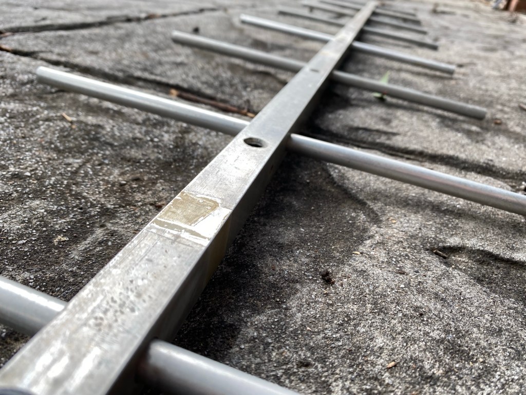
Common 15 metre antennas include dipole antennas, vertical antennas, and directional beam antennas (Yagi). A simple half-wave dipole for 15m is about 7 metres long (total length), making it relatively compact and easy to install. Vertical antennas are popular for low-angle radiation, which is ideal for long-distance DX. More advanced operators often use Yagi beams mounted on towers, which provide gain and directionality, significantly improving performance on this band.
Performance
The interaction with ionospheric layers is key to understanding 15m performance. The F1 and F2 layers are responsible for most long-distance propagation, particularly during the daytime. The D layer, which forms during daylight hours, can absorb lower-frequency signals but has less effect on 15m, helping keep noise levels lower. Occasionally, sporadic E propagation can also open the band, especially in summer, allowing unexpected medium-distance contacts even when the F layer is weak.
Band opens
The 15 metre band is generally open during daylight hours, especially from mid-morning to late afternoon. Peak performance often occurs around local noon, when the ionosphere is most ionised. Openings are more frequent during solar maximum years, and less reliable during solar minimum. The band typically closes after sunset, although limited openings can sometimes occur around greyline (sunrise and sunset), offering unique DX opportunities.
Summary
Overall, the 15 metre amateur radio band is valued for its strong DX capability, low noise levels, and relatively small antenna size requirements. It is an excellent band for both beginners and experienced operators who want to explore worldwide HF communication, especially during favourable solar conditions.
- Solar Data & Propagation
 There are several website that tell you what bands are open in your area. Most people paste them on their QRZ page, but there are some examples below that update every hour. You can see more on their webpage https://www.hamqsl.com/solar.html where all you have to do is paste the code and put on your website.…
 - NetTime
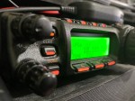
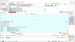
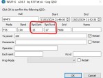
 When using digital over the radio, it is particularly important you have the correct time. Even a second out will stop you from making contacts. I relied on Windows to update the time and got an email from a helpful amateur telling me my time was out. You can see below it wasn’t out by…
 - Barefoot
 I’ve heard several amateur radio operators say they are running a Barefoot setup. But what does it mean? It has nothing to do with what is or is not on your feet. But simply means transmitting without an amplifier. While power helps, the best thing you can do to fix your signal is your antenna.…
 - Diamond Antenna W-8010 and expanding it to all bands
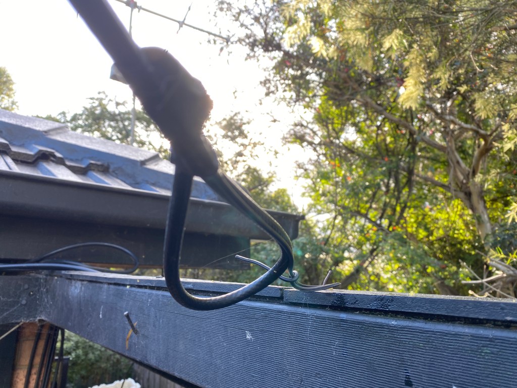
 I purchased the Diamond W series W8010 antenna and quickly put it together. The instructions were a bit hard to read as it was exceedingly small. However, I found someone who did a video on how to put it together. (this is not my video) To me, an antenna is far more important than the…
 - NanoVNA-H 4 Antenna Analyser
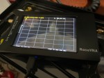 The Nano VNA-H 4 is my new toy that has just arrived after purchasing via Banggood. This Antenna Analyser is a complicated device, but doesn’t have to be, and can be a powerful tool for the Amateur Radio hobbyist. Charging the device Your NanoVNA should come with a USB cord. To charge it, simply plug…
 - DXHeat.com
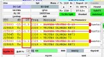
 DXHeat.com is a great website that can update you the current conditions on each band. The website has filtering of incoming DX Spots which can be displayed instantly using great graphical tools. From the main landing page dxheat.com you can do a search by call sign or open DX Cluster. You can also scroll down…
 - VARA – VARAC
 Ever heard this sound on HF / VHF / UHF? I know I have more and more recently. After a bit of research, someone told me it was VARAC. https://www.varac-hamradio.com/ As I understand it, the project started with Irad Deutsch 4Z1AC. It is free of charge for amateur radio operators. This software provides text base…
 - Converting dB to S-metre
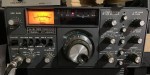
 The S-meter is an instrument on most radio receivers that measures the strength of the signal being received. It uses a unit: the S-point. HF radios usually have a needle scale, whereas other bands often have LEDs displaying the S-Points. S-Points is the common method of measuring signal strength between operators, however many programs like…
 - DNR – Digital Noise Reduction
 As per the Yaesu FT-710 manual, the Digital Noise Reduction (DNR) system is designed to reduce the level of ambient noise found on the HF and 50 MHz bands. The (DNR) system is especially effective during SSB operation. Any of 15 different noise-reduction algorithms can be selected; each of these algorithms was created to deal…
 - Portable HF all band Antenna and Mount
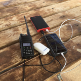
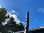 I recently got the Radioddity M916 Heavy duty antenna magnetic mound with the Radioditty HF-008 all band portable antenna. I had always wanted to use HF more while camping or going on adventures around Australia (see our adventures page if you are interested), and now I am a step closer to doing that. This quick…